Circuit Diagram To Boolean Expression. Compute a logic circuit for a boolean function. Web compute a logic circuit for a boolean function.
PPT Boolean Algebra and Logic Simplification PowerPoint Presentation from www.slideserve.com
Web analyze boolean expressions and compute truth tables. Web create a circuit diagram to represent the boolean expression q, equals, left bracket, a, and, b, right bracket, or, left bracket, c, and, d, right bracket, q = (a ∧ b) ∨ (c ∧ d). F (a, b, c) = (a’ + b + c).
Web Definition 1 (Boolean Expression Diagram).
They include both the full name, e.g. Web logic circuit diagram into boolean expression and vice versa. By a boolean algebraic expression;
Web How To Write A Boolean Expression To Simplify Circuits Our First Step In Simplification Must Be To Write A Boolean Expression For This Circuit.
A boolean expression diagram is a directed acyclic graph g = (v, e) with vertex set v and edge set e. F (a, b, c) = (a’ + b + c). Web what is a circuit diagram?
Start Diagramming With Various Templates And Symbols Easily.
Logic circuit diagram designerconsists of 3 main parts. And or not wire instructions. To illustrate this procedural method, we should begin with a realistic design problem.
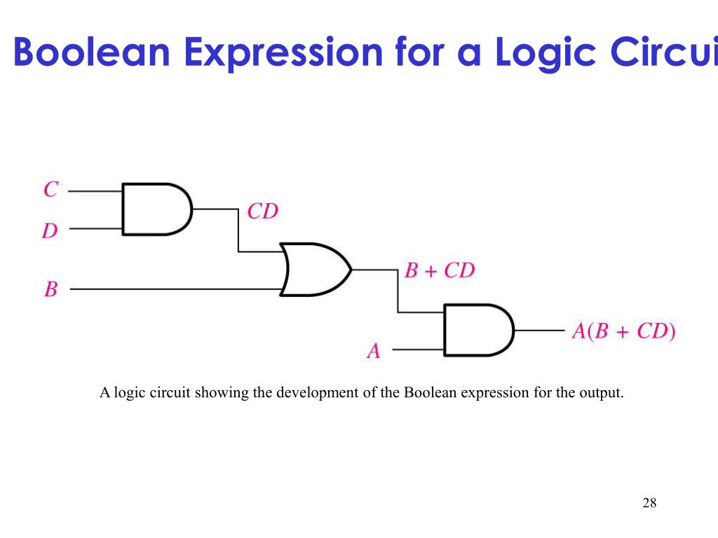
Web When A Logic Circuit Is Given, The Boolean Expression Describing That Logic Circuit Can Be Obtained By Combining The Input Variables In Accordance With The Logic Gate Functions.
Note that the rows of the truth. Perform boolean algebra by computing various properties and forms and generating various. Web draw the equivalent logic circuit diagram for the boolean expression using nor gates only :
Web Recipe For Making Combinational Circuit Ingredients.
Web compute a logic circuit for a boolean function. Web here, boolean algebra proves its utility in a most dramatic way. Represent input and output signals with boolean variables.